Mast Construction Catalogue
Home » Pole construction » Mast Construction Catalogue
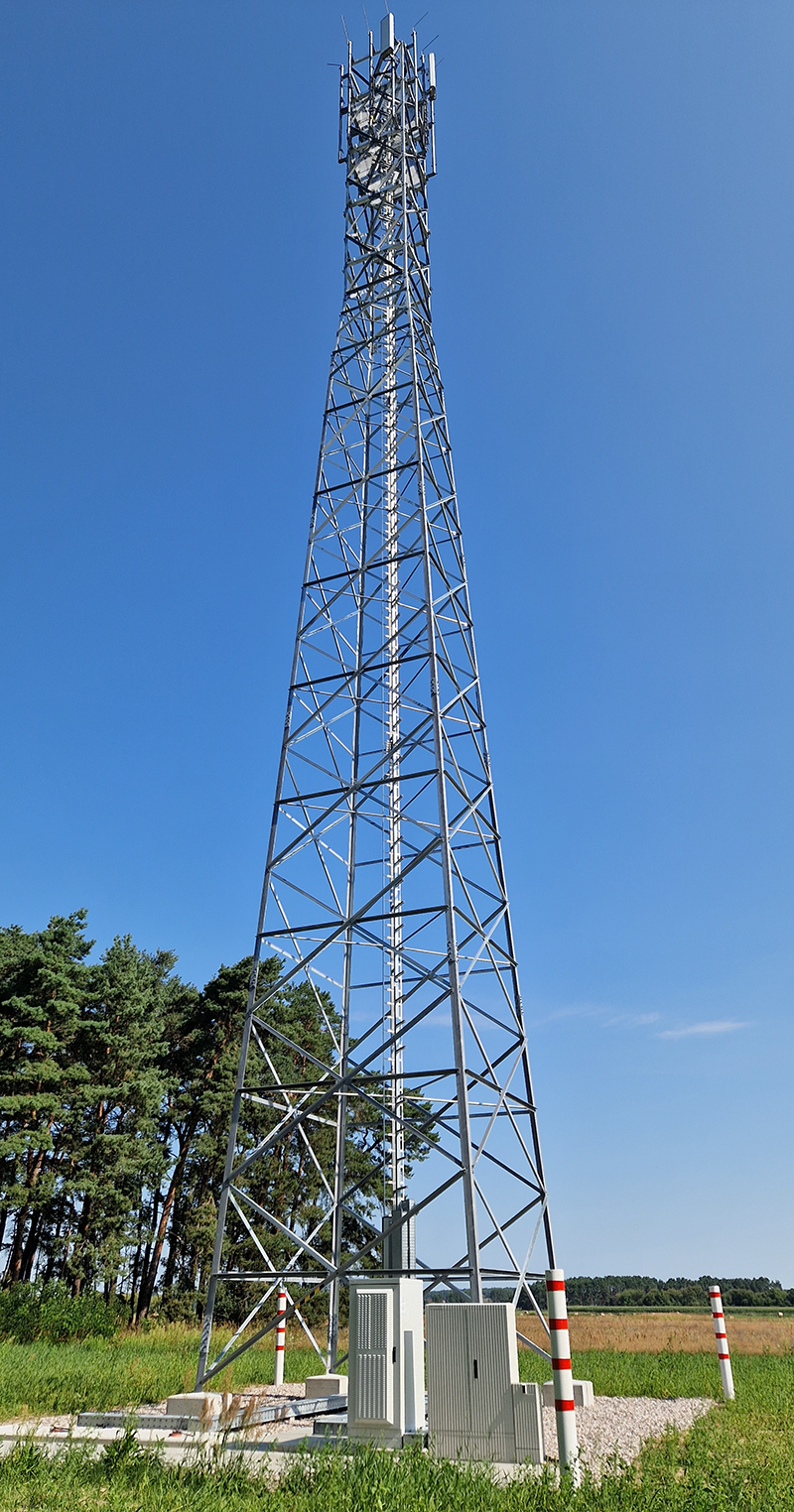
Our masts
Our customers are as unique as their individual requirements: No two sites are alike. Accordingly, we are committed to finding mast solutions that are ideally tailored to your specific conditions and requirements. We can draw on a wide range of masts that can be customised to your needs thanks to modular adaptations. And in spots where our tried-and-tested solutions are not feasible, we will find the right bespoke concept.
Below, we would like to introduce you to our proven mast ranges:
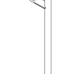
MGT200
Basically, the MGT200 was designed for special applications:
- At (large-scale) functions and events;
- During building renovations and the conversion, optimisation and modernisation of radio locations;
- When tenancy agreements are terminated or expire; and
- To maintain network operations following severe weather events.
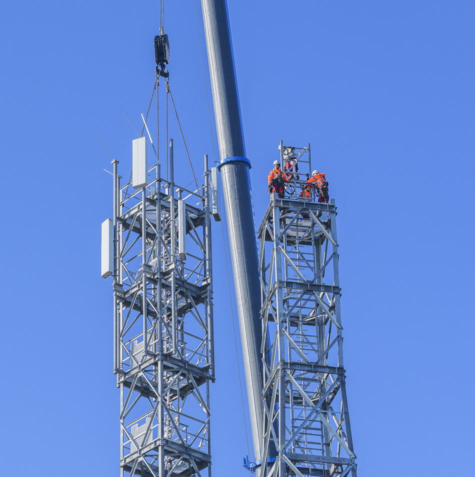
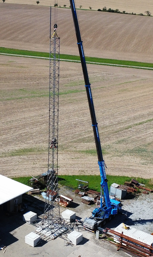
It is characterised in particular by its adaptability: It can be used flexibly as a temporary installation (“mobile structure”) for up to two years. The prefabricated mast elements also allow for very rapid assembly.
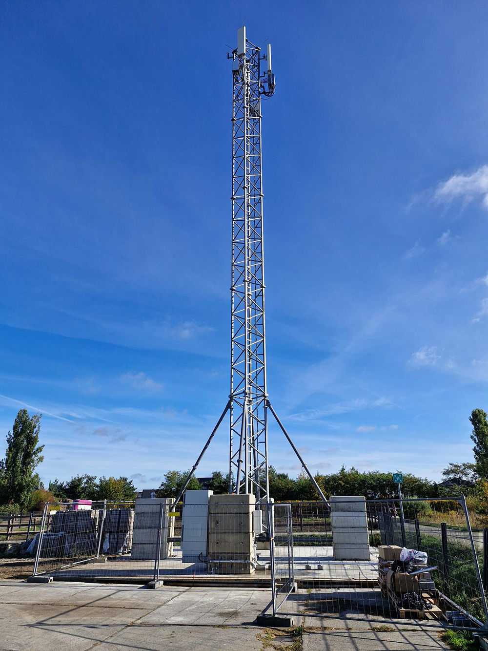
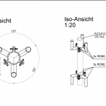
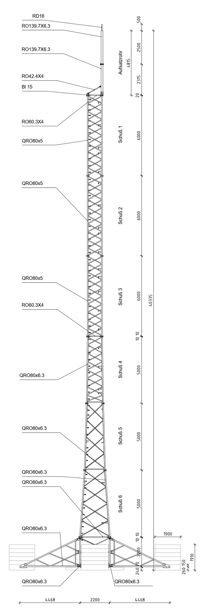
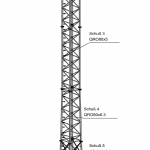
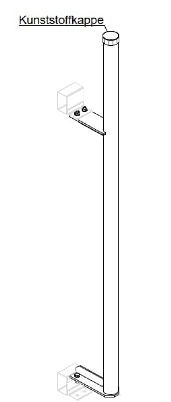
The MGT200 is a steel lattice mast with a tower height between 20 and 30 metres. It features an additional five-metre tubular extension. The structure consists of hollow and angle sections as well as an internal ladder.
read moreless
| Mast heights | |||||
|---|---|---|---|---|---|
|
System height [m] |
20 |
25 |
30 |
30+5 |
|
|
Gewicht [kg] |
2550 |
3150 |
3750 |
3950 |
|
| Footprint; each mast type can be extended with a tubular extension of up to 6 metres in length | |||||
|---|---|---|---|---|---|
|
Temporary installation |
Mast [m²] |
26 |
15 |
8 |
2 |
|
Tubular extension [m²] |
|
|
|
3 |
|
|
Permanent installation |
Mast [m²] |
17,25 |
9 |
2,5 |
|
|
Tubular extension [m²] |
|
|
|
1,5 |
|
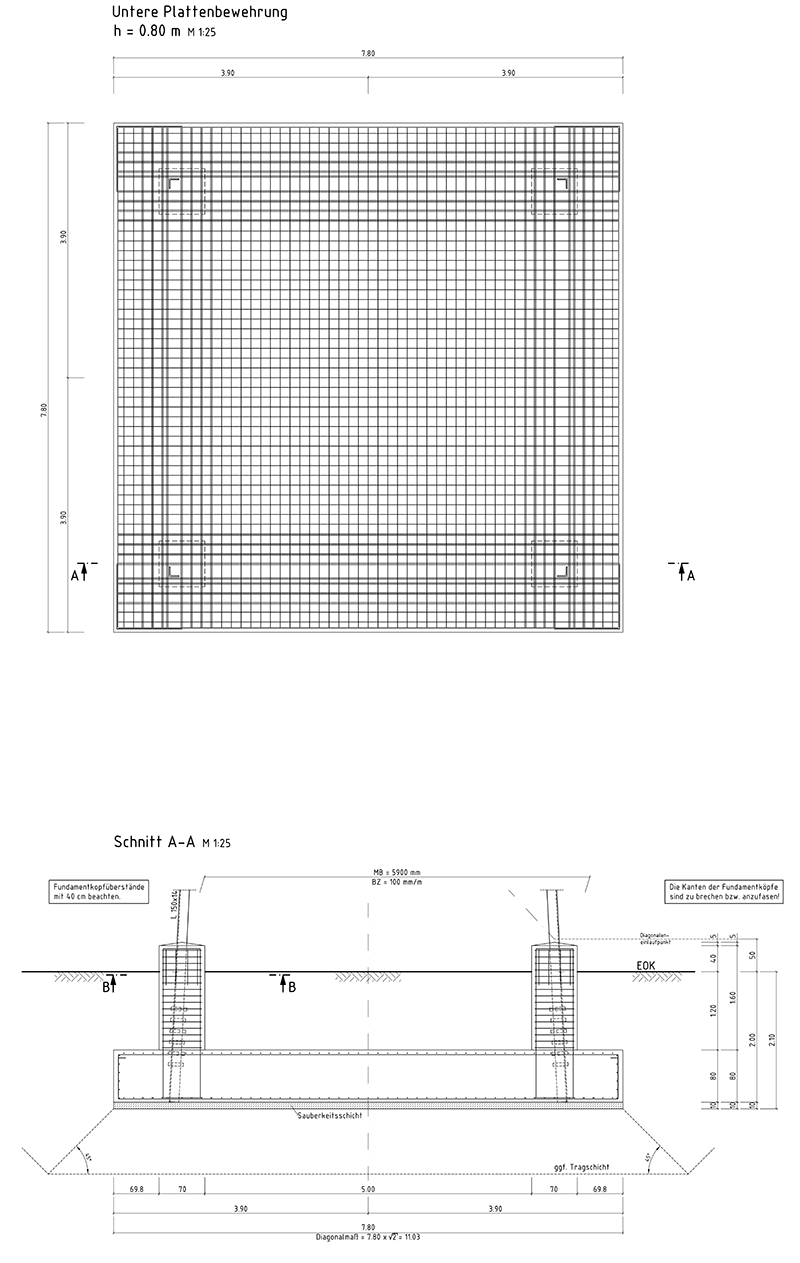
| Foundations; load-bearing foundations made of precast reinforced concrete elements | |||||
|---|---|---|---|---|---|
|
Base |
Width/Length [m] |
1,20 |
|||
|
Slab thickness [m] |
0,5 |
||||
|
Loard-bearing element |
Width/Length [m] |
1,2 |
|||
|
Slab thickness [m] |
0,5 |
||||
| Attachment parts | |||||
|---|---|---|---|---|---|
|
Tubular extension |
Length [m] |
5 |
|||
|
Cross-section [mm] |
139,7 |
||||
|
Gewicht [kg] |
100 |
||||
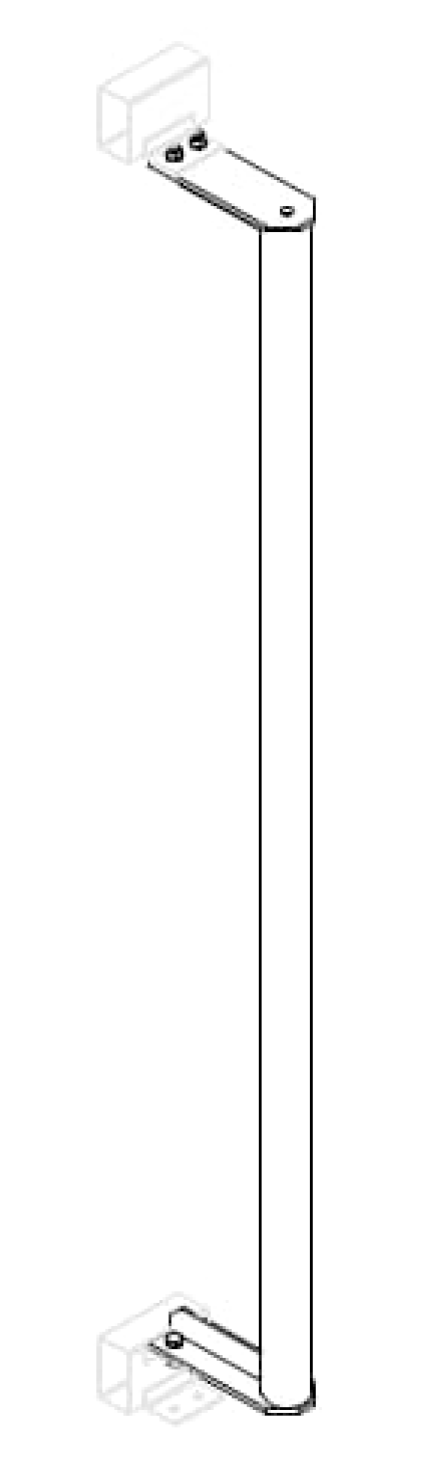
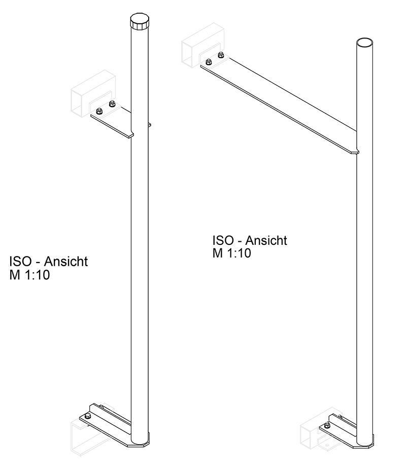
|
Support tubes |
Amount |
Site-specific selection of several pre-assembled cantilever structures for directional and sector antennas available for both corner leg installation and the tubular extension |
|||
|
Platform |
|||||
|
Length [mm] |
|||||
|
Overhang [mm] |
|||||
|
Cross-section [mm] |
|||||
|
Gewicht [kg] |
|||||
| Implementation times | |||||
|---|---|---|---|---|---|
|
Site survey |
Prerequisites |
Order intake |
|||
|
Calendar days |
14 |
||||
|
Conceptual design |
Prerequisites |
Carrying out the structural inspection |
|||
|
Calendar days |
45 |
||||
|
Detailed design |
Prerequisites |
Approval of the conceptual design |
|||
|
Calendar days |
14 |
||||
|
Start of construction |
Prerequisites |
Approval of the detailed design |
|||
|
Calendar days |
30 |
||||
|
Construction period |
Prerequisites |
Start of construction |
|||
|
Calendar days |
20 |
||||
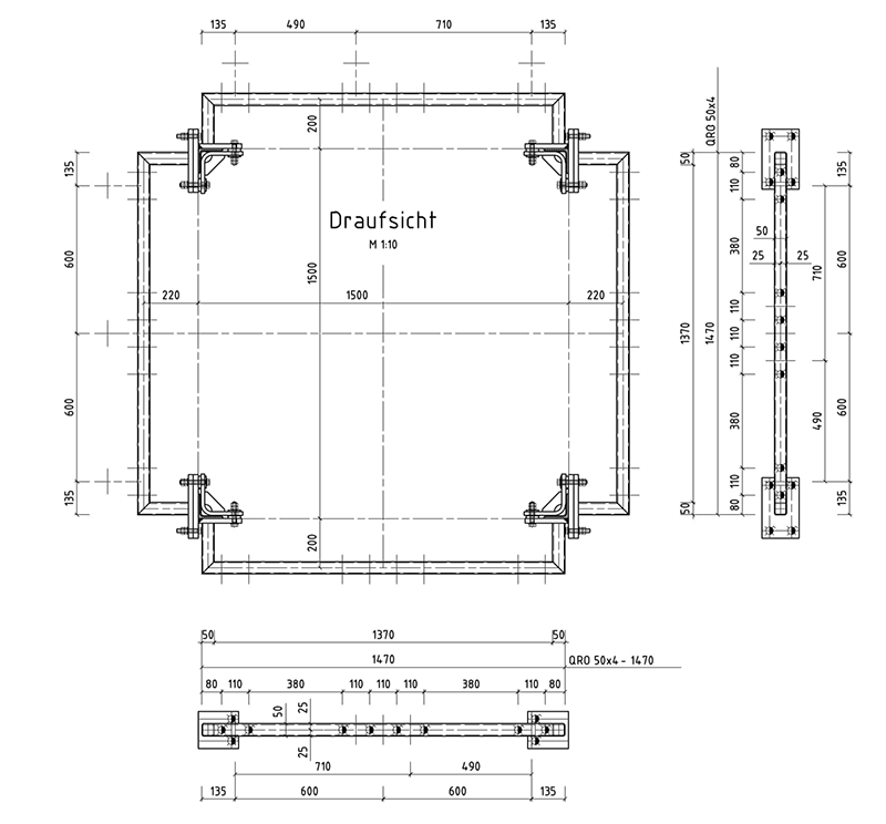
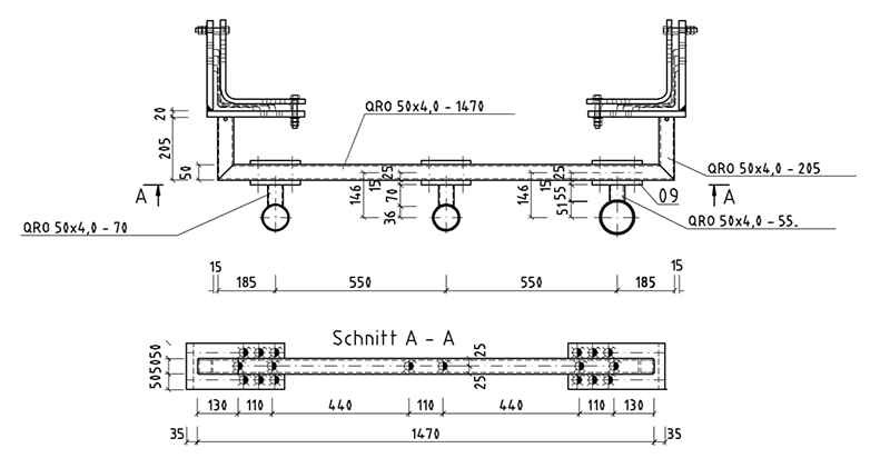
Standards:
- Verification in accordance with DIN EN 1993-3;
- Wind zone II;
- Terrain category II/III
- Ice zone IV.
-
- Systemzeichnung MGT200
-
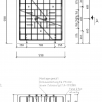
- Grundstein MGT200
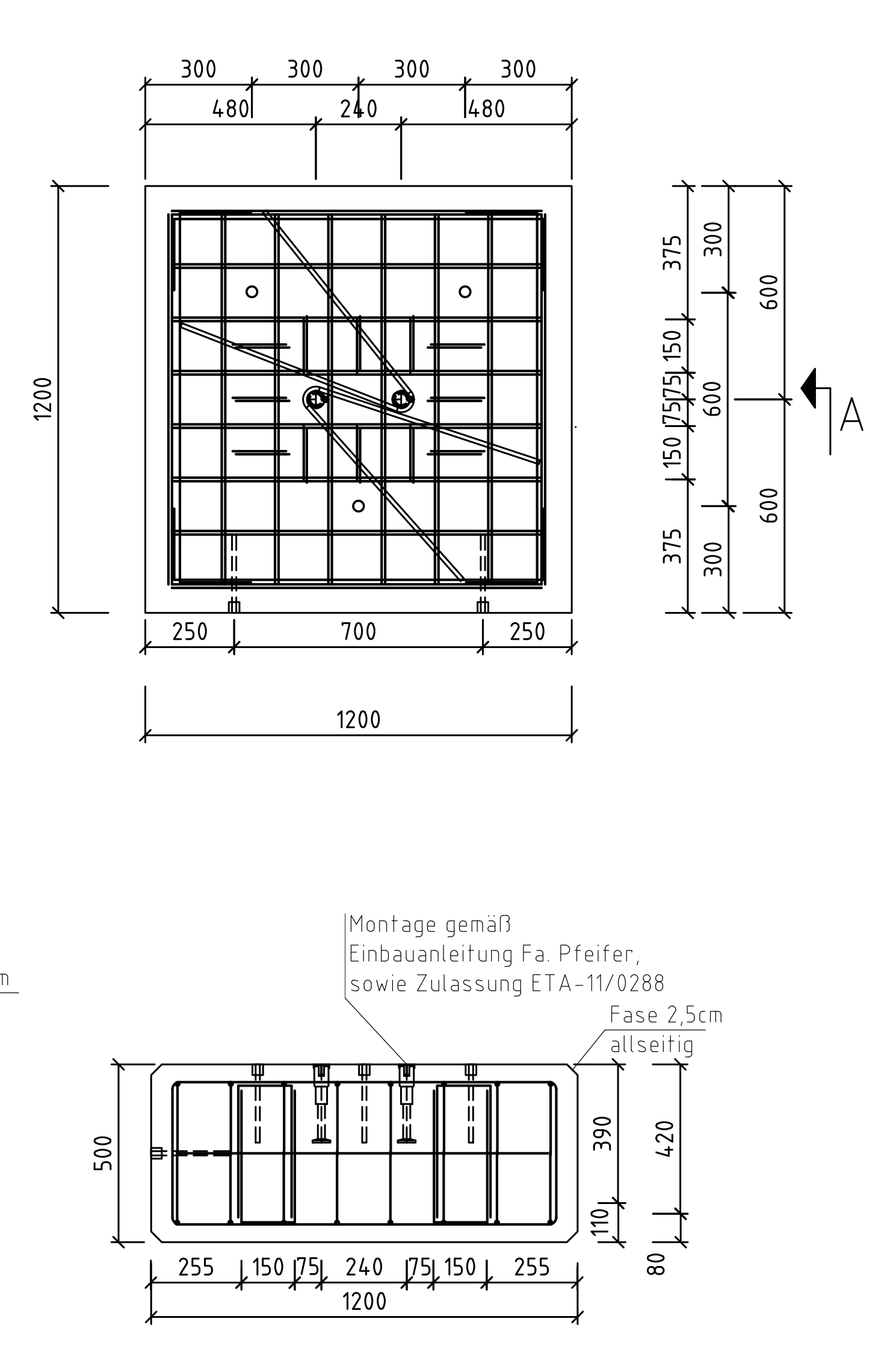
-
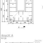
- Auflastelemente MGT200
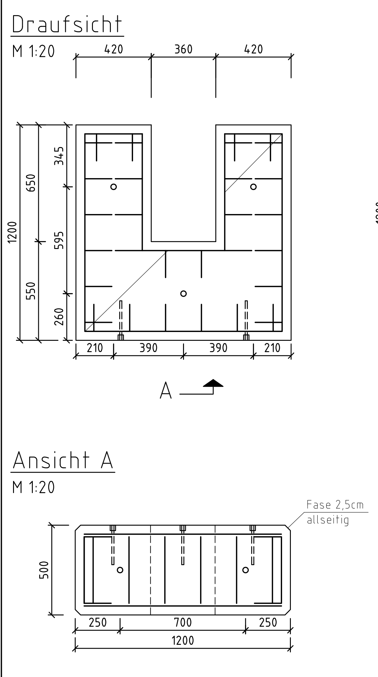
-
- Tragrohre für Aufsatzrohr MGT200
-
- Tragrohre für Eckstiel MGT200
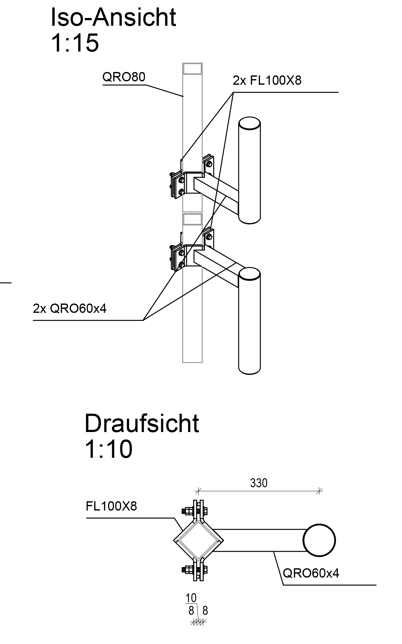
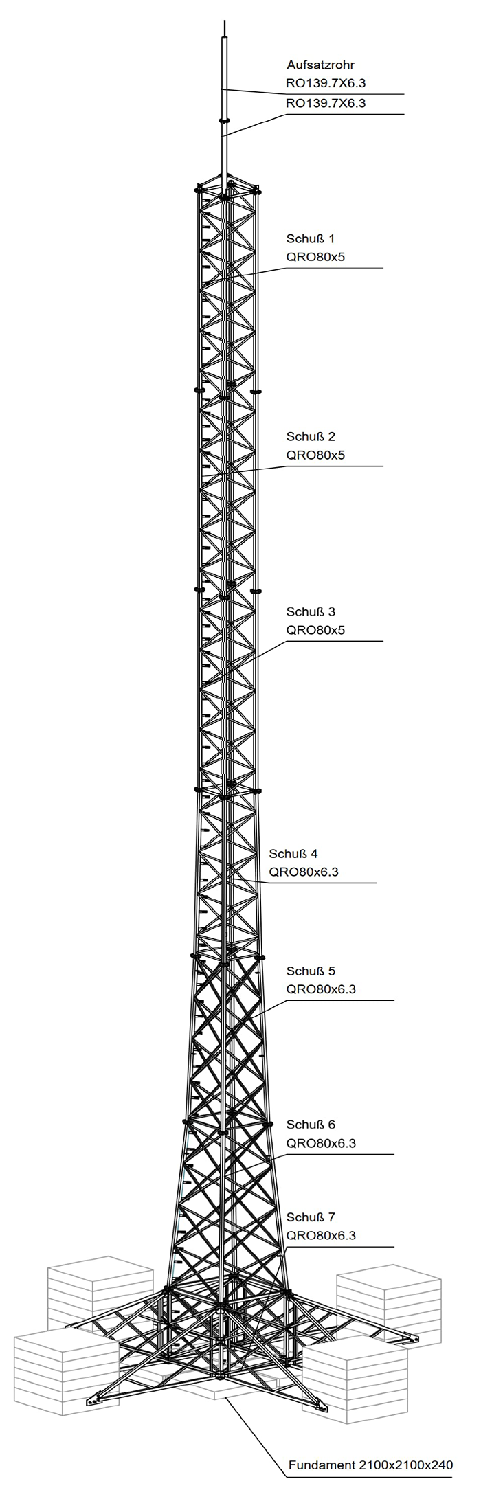
MGT400
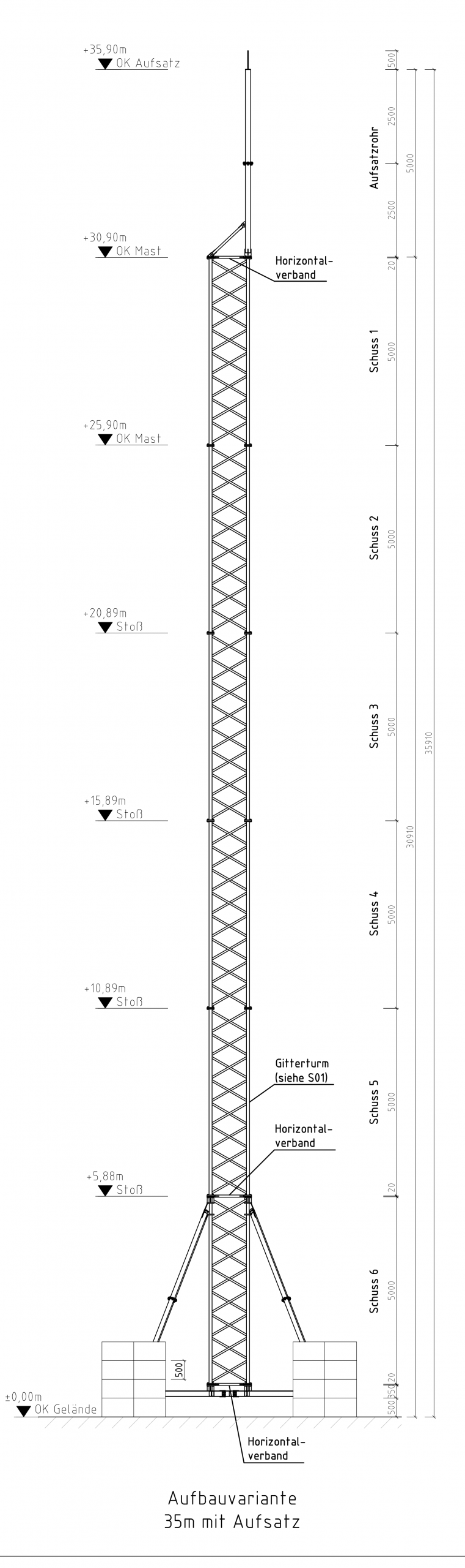
The MGT400 is the big brother of the MGT200: While possessing all the qualities of the MGT200, it reaches tower heights of 22, 29, and 35 metres. It is therefore also ideally suited for special applications:
- At (large-scale) functions and events;
- During building renovations and the conversion, optimisation and modernisation of radio locations;
- When tenancy agreements are terminated or expire; and
- To maintain network operations following severe weather events.
Based on the prefabricated mast elements, the steel lattice mast, which consists of hollow and angle sections with an internal ladder, can be erected quickly. As a temporary installation (“temporary structure”), it can be used for up to two years. A building permit is required for a permanent installation.
read moreless
| Mast heights | |||||
|---|---|---|---|---|---|
|
System height [m] |
22 |
29 |
35 |
35+5 |
|
|
Gewicht [kg] |
5050 |
5700 |
6350 |
6500 |
|
| Footprint; each mast type can be extended with a tubular extension of up to 6 metres in length | |||||
|---|---|---|---|---|---|
|
Temporary installation |
Mast [m²] |
15 |
10,5 |
7 |
3,5 |
|
Tubular extension [m²] |
|
|
|
2,5 |
|
|
Permanent installation |
Mast [m²] |
15 |
10,5 |
7 |
3,5 |
|
Tubular extension [m²] |
|
|
|
2,5 |
|
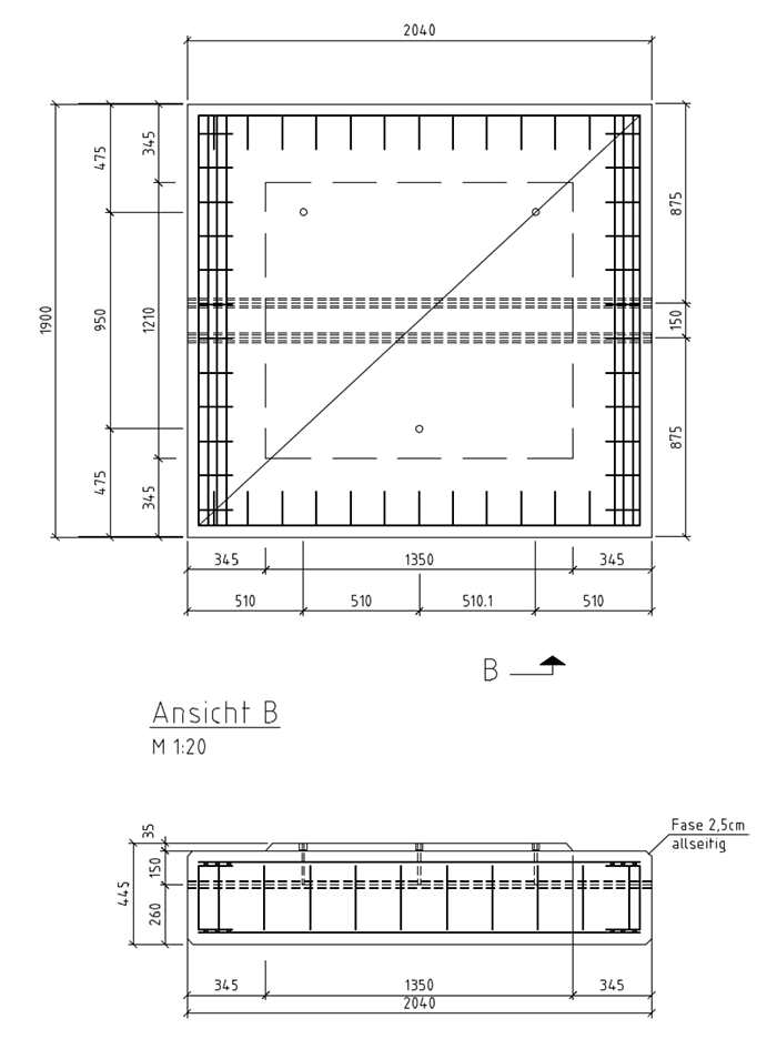
| Foundations; load-bearing foundations made of precast reinforced concrete elements | |||||
|---|---|---|---|---|---|
|
Base |
Width x Length [m] |
2,04 x 1,9 |
|||
|
Slab thickness [m] |
0,45 |
||||
|
Loard-bearing element |
Width x Length [m] |
2,04 x 1,9 |
|||
|
Slab thickness [m] |
0,34 |
||||
| Attachment parts | |||||
|---|---|---|---|---|---|
|
Tubular extension |
Length [m] |
5 |
|||
|
Cross-section [mm] |
139,7 x 6,3 |
||||
|
Gewicht [kg] |
120 |
||||
|
Support tubes |
Amount |
Site-specific selection of several pre-assembled cantilever structures for directional and sector antennas available for both corner leg installation and the tubular extension |
|||
|
Platform |
|||||
|
Length [mm] |
|||||
|
Overhang [mm] |
|||||
|
Cross-section [mm] |
|||||
|
Gewicht [kg] |
|||||
| Implementation times | |||||
|---|---|---|---|---|---|
|
Site survey |
Prerequisites |
Order intake |
|||
|
Calendar days |
14 |
||||
|
Conceptual design |
Prerequisites |
Carrying out the structural inspection |
|||
|
Calendar days |
45 |
||||
|
Detailed design |
Prerequisites |
Approval of the conceptual design |
|||
|
Calendar days |
14 |
||||
|
Start of construction |
Prerequisites |
Approval of the detailed design |
|||
|
Calendar days |
30 |
||||
|
Construction period |
Prerequisites |
Start of construction |
|||
|
Calendar days |
20 |
||||
Standards:
- Verification in accordance with DIN EN 1993-3;
- Wind zone II;
- Terrain category II/III
- Ice zone IV.
-
- Systemzeichnung mit Masthöhe 35m
-
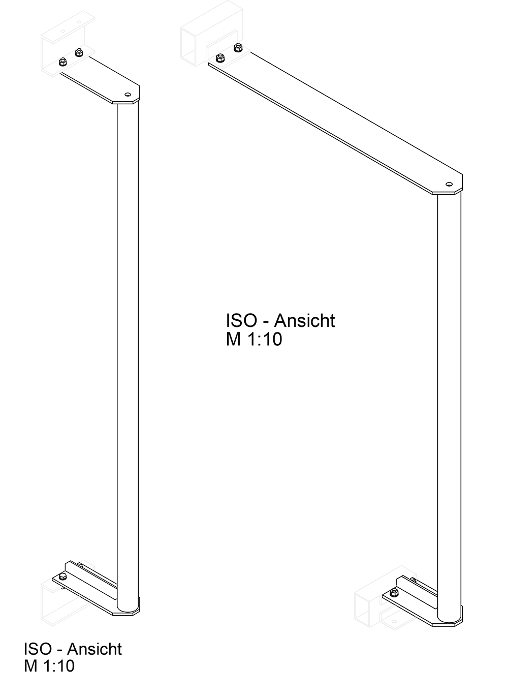
- Isometrie MGT400
-
- Auflastelemente MGT400
-
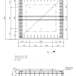
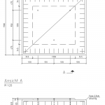
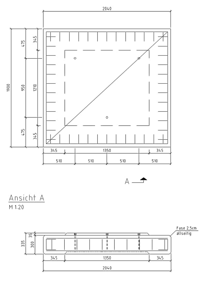
- Grundstein MGT400
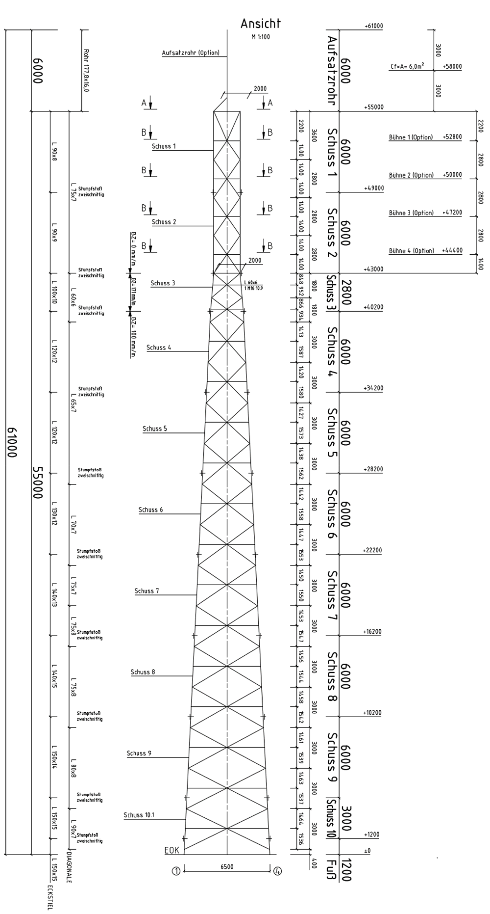
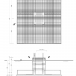
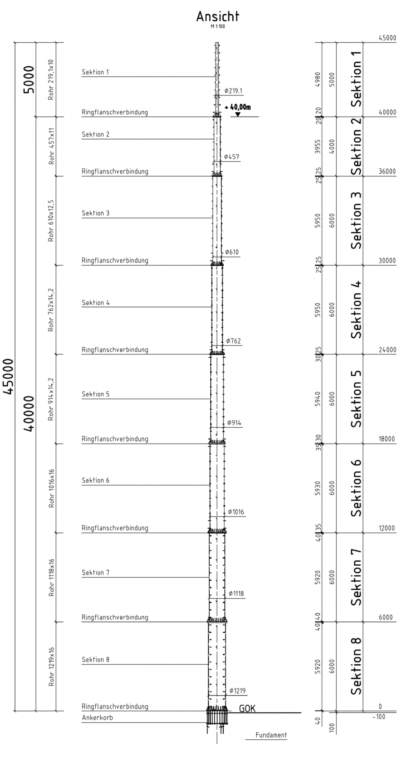
EEW
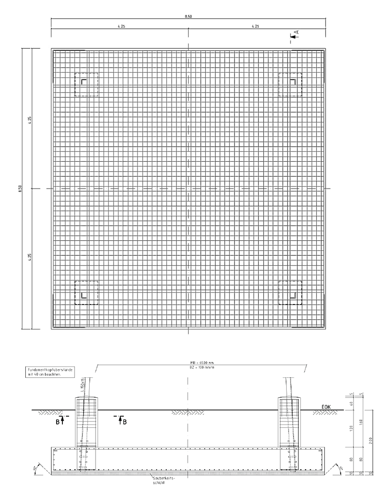
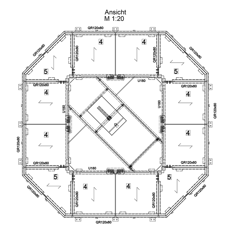
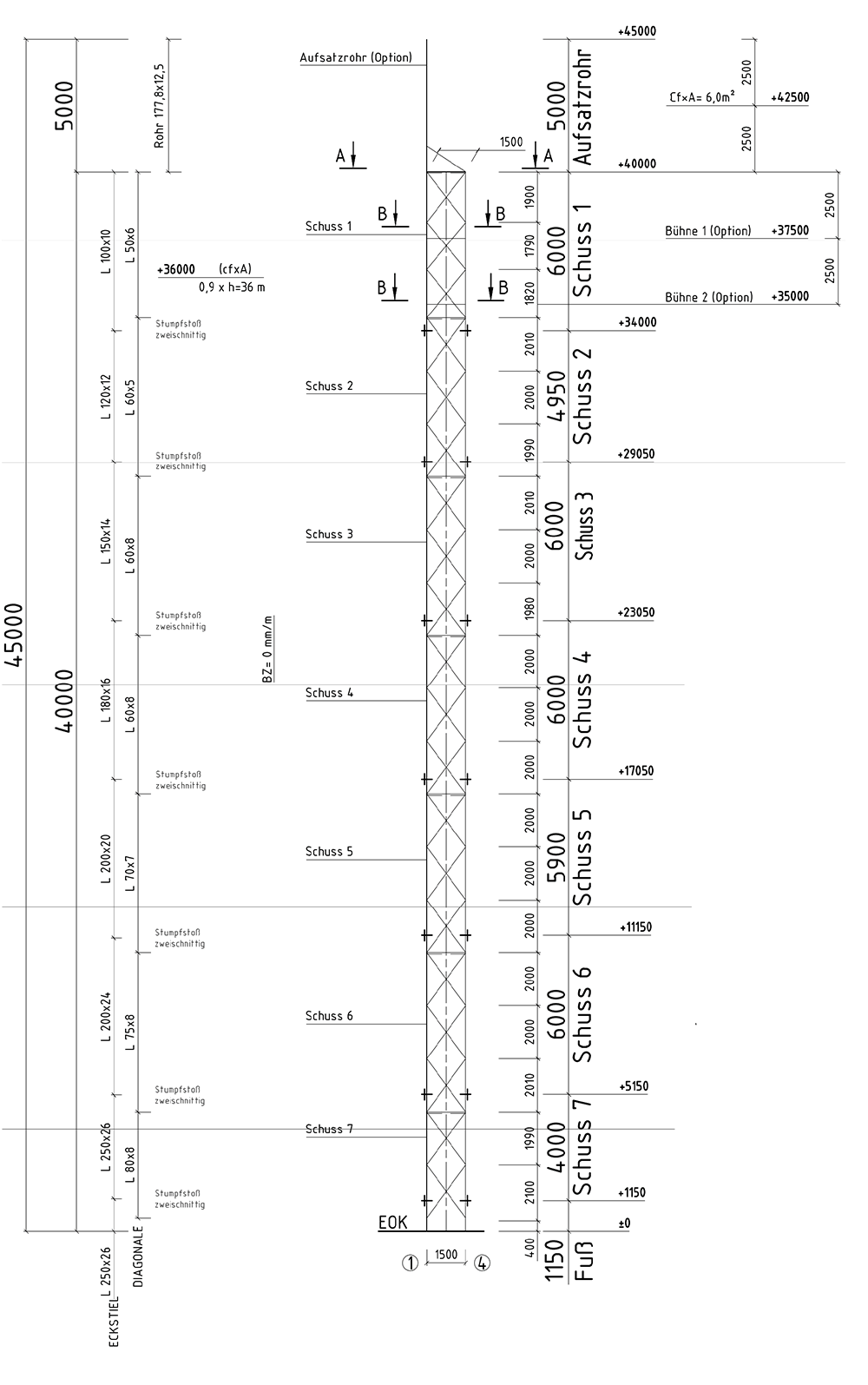
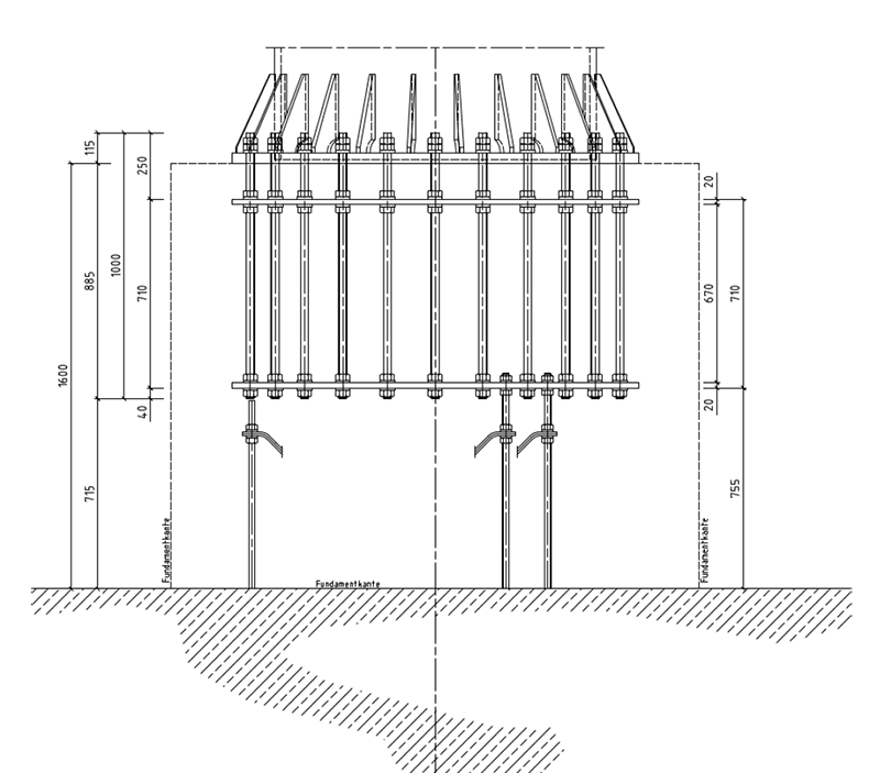
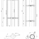
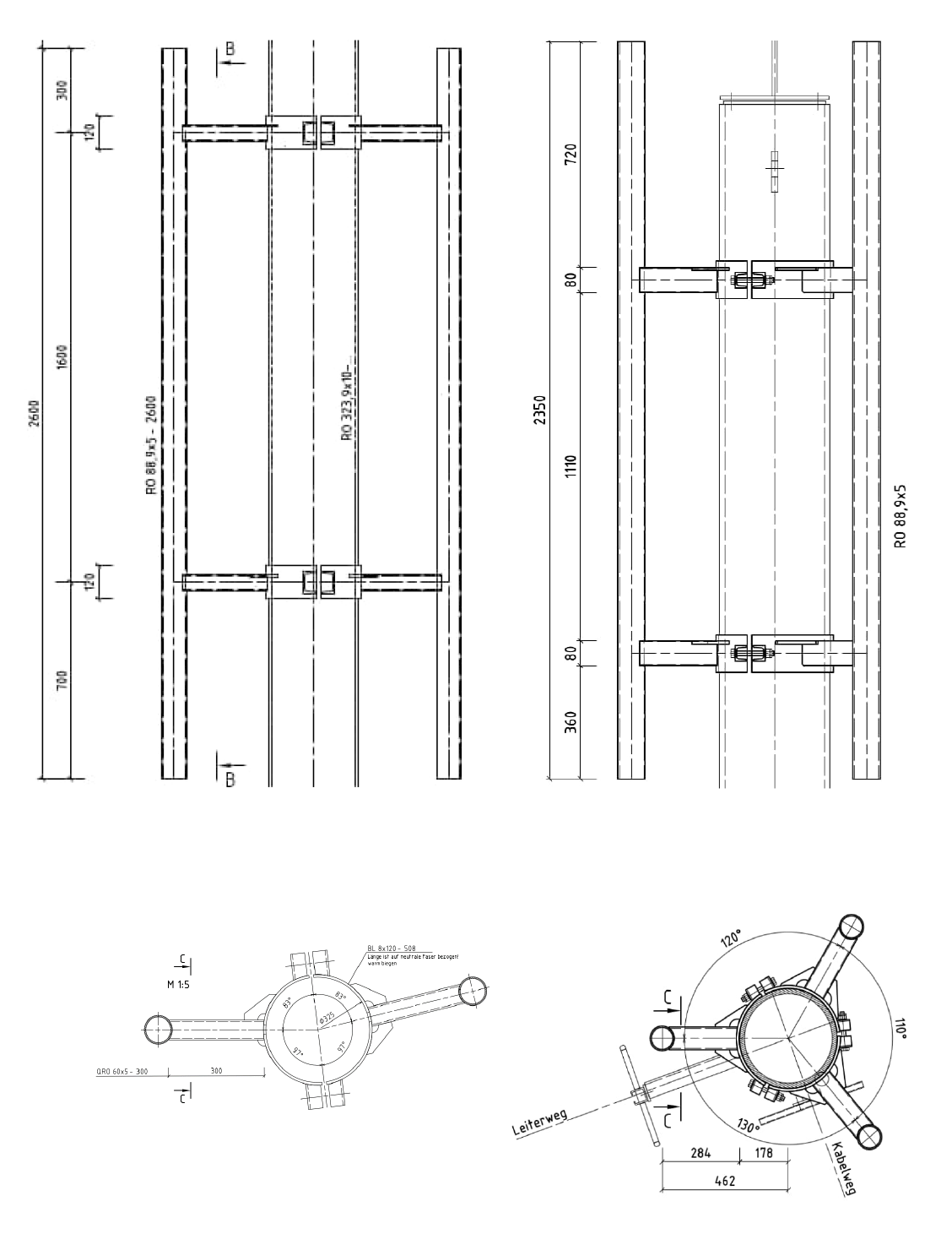
The EEW is not only highly efficient but, above all, versatile. The height of the steel lattice mast ranges from 30 to 55 metres. The additional tubular extension is 6 metres long. Thanks to our flexible 3D software model, adjustments can be made easily upon request to meet the local conditions. Additional platforms are also possible to reduce the footprint. The mast, which consists of angle sections, is generally equipped with four internal platforms, and its antenna spacing is 0.9*h.
read moreless
| Mast heights | |||||||
|---|---|---|---|---|---|---|---|
|
System height [m] |
30 |
35 |
40 |
45 |
50 |
55 |
|
|
Gewicht [kg] |
7690 |
9270 |
11320 |
12890 |
15250 |
17990 |
|
| Footprint; each mast type can be extended with a tubular extension of up to 6 metres in length | ||||||||
|---|---|---|---|---|---|---|---|---|
|
Mast [m²] |
26 |
23,5 |
22,5 |
22 |
22 |
21,5 |
||
|
Tubular extension [m²] |
6 |
|||||||
| Foundations; embedment depth 2m | |||||||
|---|---|---|---|---|---|---|---|
|
Without buoyancy |
Width/Length [m] |
6 |
6,5 |
7 |
7,5 |
8 |
8,5 |
|
Slab thickness [m] |
0,6 |
0,7 |
0,7 |
0,7 |
0,8 |
0,8 |
|
|
With full buoyancy |
Width/Length [m] |
7 |
7,6 |
8,2 |
8,8 |
9,4 |
10 |
|
Slab thickness [m] |
0,6 |
0,7 |
0,8 |
0,8 |
0,8 |
0,8 |
|
| Attachment parts | |||||||
|---|---|---|---|---|---|---|---|
|
Tubular extension |
Length [m] |
6 |
|||||
|
Cross-section [mm] |
177,8 x 16 |
||||||
|
Gewicht [kg] |
440 |
||||||
|
Platforms |
Amount |
4 |
|||||
|
Gewicht [kg] |
125 |
||||||
|
Support tubes |
Amount |
maximum of 12 per platform |
|||||
|
Platform |
1st platform (top) |
2nd-.4th platform (top) |
|||||
|
Sector |
Directional radio |
Sector |
Directional radio |
||||
|
Length [mm] |
2700 |
2700 |
2700 |
2660 |
2660 |
2660 |
|
|
Overhang [mm] |
285 |
285/500 |
300 |
305 |
285 |
300 |
|
|
Cross-section [mm] |
114,3 x 6,3 |
88,9 x 5 |
114,3 x 6,3 |
114,3 x 6,3 |
88,9 x 5 |
114,3 x 6,3 |
|
|
Gewicht [kg] |
63 |
40/47 |
103 |
60 |
40 |
101 |
|
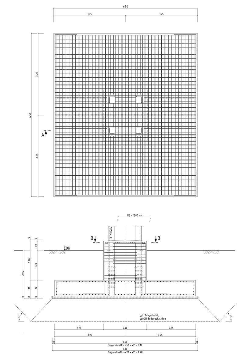
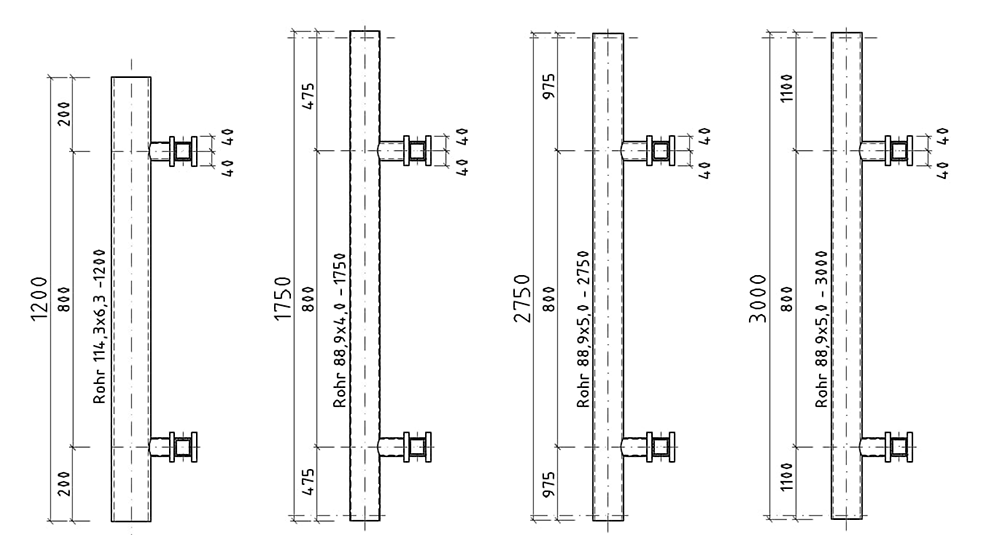
Standards:
- Verification in accordance with DIN EN 1993-3;
- Wind zone II;
- Terrain category II/III
- Ice zone IV.
-
- Systemzeichnung mit Masthöhe 55m EEW
-
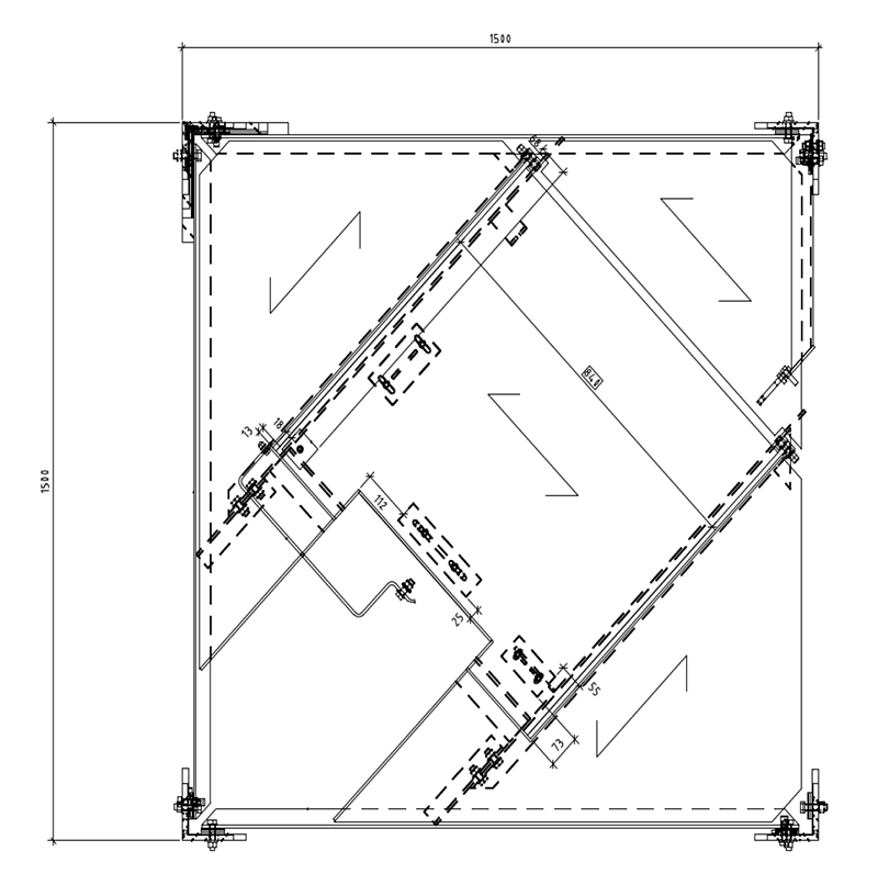
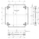
- Bühne EEW
-
- Fundament EEW
-
- Tragrohr für die 1. Bühne EEW
-
- Tragrohr für die 2.-4. Bühne EEW
| Implementation times | |||||
|---|---|---|---|---|---|
|
Site survey |
Prerequisites |
Order intake |
|||
|
Calendar days |
14 |
||||
|
Conceptual design |
Prerequisites |
Carrying out the structural inspection |
|||
|
Calendar days |
45 |
||||
|
Building permit procedure |
Prerequisites |
Approval of the conceptual design |
|||
|
Calendar days |
14 |
||||
|
Detailed design |
Prerequisites |
Obtaining building permit |
|||
|
Calendar days |
14 |
||||
|
Start of construction |
Prerequisites |
Approval of the detailed design |
|||
|
Calendar days |
40 |
||||
|
Construction period |
Prerequisites |
Start of construction |
|||
|
Calendar days |
100 |
||||
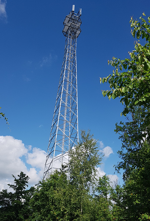
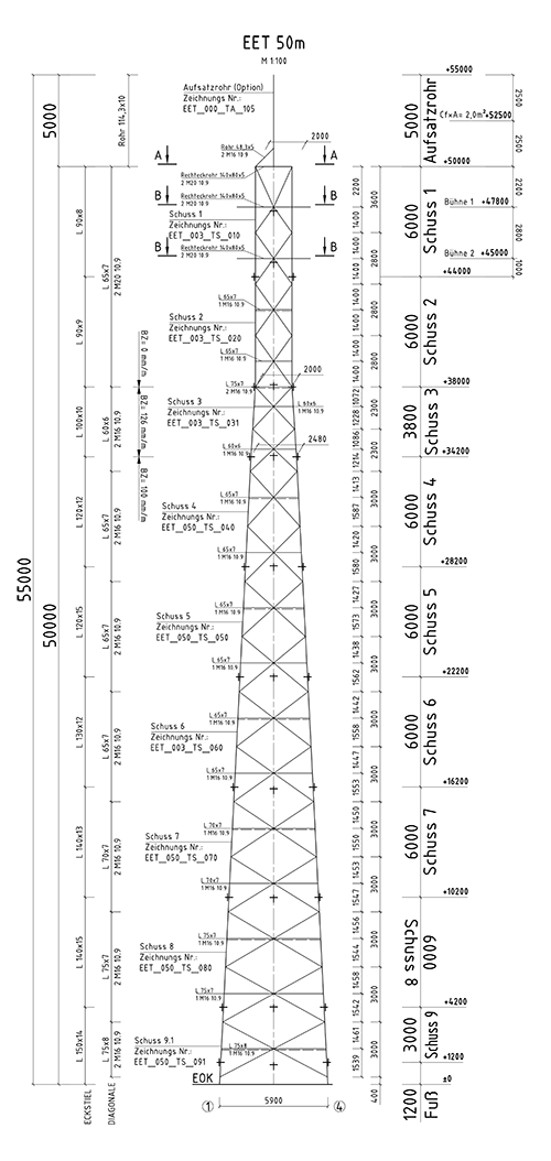
EET
The EET is similar to the EEW in many respects. The steel lattice mast has a tower height of 30 to 50 metres with an additional 6-metre tubular extension. The antenna spacing is also 0.9*h; it features internal access ladders and is equally flexible, efficient, and versatile. The primary difference lies in the platform configuration, since the EET features two internal platforms that can also be extended to serve as external platforms. Additional platforms are possible and reduce the footprint. Here, too, customisation to your requirements and local conditions is possible thanks to the flexible 3D software model.
read moreless
| Mast heights | |||||
|---|---|---|---|---|---|
|
System height [m] |
30 |
35 |
40 |
50 |
|
|
Gewicht [kg] |
3850 |
5540 |
7550 |
11560 |
|
| Footprint; each mast type can be extended with a tubular extension of up to 6 metres in length | ||||||||
|---|---|---|---|---|---|---|---|---|
|
Mast [m²] |
23 |
23 |
23 |
23 |
||||
|
Tubular extension [m²] |
2 |
|||||||
| Foundations; embedment depth 2m | |||||
|---|---|---|---|---|---|
|
Without buoyancy |
Width/Length [m] |
5,8 |
6,3 |
6,8 |
7,8 |
|
Slab thickness [m] |
0,5 |
0,6 |
0,7 |
0,8 |
|
|
With full buoyancy |
Width/Length [m] |
6,8 |
7,4 |
8 |
9,2 |
|
Slab thickness [m] |
0,5 |
0,6 |
0,7 |
0,8 |
|
| Attachment parts | |||||
|---|---|---|---|---|---|
|
Tubular extension |
Length [m] |
6 |
|||
|
Cross-section [mm] |
177,8 x 12,5 |
||||
|
Gewicht [kg] |
304 |
||||
|
Platforms |
Amount |
2 (external and internal platform) |
|||
|
Gewicht [kg] |
218 (internal); 775 (external) |
||||
|
Support tubes |
Amount |
maximum of 12 per platform |
|||
|
Platform |
1st platform (top) |
2nd platform |
|||
|
Sector |
Directional radio |
Sector & directional radio |
|||
|
Length [mm] |
2700 |
2000 |
2600 |
||
|
Overhang [mm] |
365 |
365 |
365 |
||
|
Cross-section [mm] |
88,9 x 5 |
88,9 x 5 |
88,9 x 5 |
||
|
Gewicht [kg] |
60 |
53 |
45 |
||
| Implementation times | |||||
|---|---|---|---|---|---|
|
Site survey |
Prerequisites |
Order intake |
|||
|
Calendar days |
14 |
||||
|
Conceptual design |
Prerequisites |
Carrying out the structural inspection |
|||
|
Calendar days |
45 |
||||
|
Building permit procedure |
Prerequisites |
Approval of the conceptual design |
|||
|
Calendar days |
14 |
||||
|
Detailed design |
Prerequisites |
Obtaining building permit |
|||
|
Calendar days |
14 |
||||
|
Start of construction |
Prerequisites |
Approval of the detailed design |
|||
|
Calendar days |
40 |
||||
|
Construction period |
Prerequisites |
Start of construction |
|||
|
Calendar days |
100 |
||||
Standards:
- Verification in accordance with DIN EN 1993-3;
- Wind zone II;
- Terrain category II/III
- Ice zone IV.
-
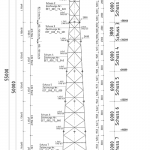
- Systemzeichnung Masthöhe
-
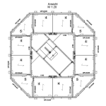
- Außen-/Innenbühne EET
-
- Tragrohre der 1. Bühne EET
EEWA
The EEWA is the even more flexible version of the EEW: This steel lattice tower, which can reach heights of up to 40 metres, really comes in handy in confined spaces. Thanks to our flexible 3D software model, adjustments can be made easily upon request to meet the local conditions. Additional platforms are also possible to reduce the footprint. For the platform constructions, there is a bolted variant (2.5 metres and 5 metres below the top of the tower) as well as a clamped variant (variable mounting height). Depending on the application – whether directional radio, sector antenna or system components close to the antenna such as remote radio units – different support tube lengths can be used. Just as with the EEW, the steel lattice mast construction with an internal ladder consists of angle sections, with an antenna spacing of 0.9*h.

read moreless
| Mast heights | |||||
|---|---|---|---|---|---|
|
System height [m] |
20 |
25 |
30 |
35 |
40 |
|
Gewicht [kg] |
3850 |
5550 |
6600 |
10850 |
14550 |
| Footprint; each mast type can be extended with a tubular extension of up to 5 metres in length | ||||||
|---|---|---|---|---|---|---|
|
Mast [m²] |
24 |
22 |
20 |
23 |
20 |
|
|
Tubular extension [m²] |
6 |
|||||
| Foundations; embedment depth 2m | ||||||
|---|---|---|---|---|---|---|
|
Without buoyancy |
Width/Length [m] |
4 |
5 |
5,5 |
6,1 |
6,5 |
|
Slab thickness [m] |
0,5 |
0,5 |
0,6 |
0,7 |
0,7 |
|
|
With full buoyancy |
Width/Length [m] |
5,2 |
5,9 |
6,5 |
7,1 |
7,6 |
|
Slab thickness [m] |
0,5 |
0,5 |
0,6 |
0,7 |
0,7 |
|
| Attachment parts | |||||
|---|---|---|---|---|---|
|
Tubular extension |
Length [m] |
5 |
|||
|
Cross-section [mm] |
177,8 x 8 |
||||
|
Gewicht [kg] |
220 |
||||
|
Platforms |
Amount |
2 |
|||
|
Gewicht [kg] |
62 |
||||
|
Support tubes |
Amount |
maximum of 12 per platform |
|||
|
|
Sector |
Directional radio |
|||
|
Length [mm] |
1750 |
2750 |
3000 |
1200 |
|
|
Overhang [mm] |
122 or 244 |
122 or 244 |
|||
|
Cross-section [mm] |
88,9 x 4 |
88,9 x 5 |
88,9 x 5 |
114,3 x 6,3 |
|
|
Gewicht [kg] |
24 |
38 |
40 |
29 |
|
| Implementation times | |||||
|---|---|---|---|---|---|
|
Site survey |
Prerequisites |
Order intake |
|||
|
Calendar days |
14 |
||||
|
Conceptual design |
Prerequisites |
Carrying out the structural inspection |
|||
|
Calendar days |
45 |
||||
|
Building permit procedure |
Prerequisites |
Approval of the conceptual design |
|||
|
Calendar days |
14 |
||||
|
Detailed design |
Prerequisites |
Obtaining building permit |
|||
|
Calendar days |
14 |
||||
|
Start of construction |
Prerequisites |
Approval of the detailed design |
|||
|
Calendar days |
40 |
||||
|
Construction period |
Prerequisites |
Start of construction |
|||
|
Calendar days |
100 |
||||
Standards:
- Verification in accordance with DIN EN 1993-3;
- Wind zone II;
- Terrain category II/III
- Ice zone IV.
-
- Systemzeichnung Masthöhe 40m EEWA
-

- Bühne EEWA
-
- Fundament EEWA
-
- Grundrahmen umlaufend EEWA
-
- Grundrahmen einzeln EEWA

EER
The EER is a steel tubular mast with a tower height between 10 and 40 metres. The additional tubular extension is 5 metres long. What makes it special is that the antenna spacing can be customised. It is also versatile and can be installed quickly and easily. Furthermore, its appearance is very unobtrusive. The ladder is mounted on the outside, and external platforms can be customised.
read moreless
| Mast heights | |
|---|---|
|
System height [m] |
10 to 40m in 5m gradation |
|
Gewicht [kg] |
Site-specific depending on antenna spacing and site |
| Footprint; each mast type can be extended with a tubular extension of up to 6 metres in length | |
|---|---|
|
Mast [m²] |
as requested by customer |
|
Tubular extension [m²] |
|
| Foundations | ||
|---|---|---|
|
Without buoyancy |
Width/Length [m] |
Site-specific block foundation, depending on ground conditions and antenna spacing |
|
Slab thickness [m] |
||
|
With full buoyancy |
Width/Length [m] |
|
|
Slab thickness [m] |
||
| Attachment parts | |||||
|---|---|---|---|---|---|
|
Tubular extension |
Length [m] |
5 |
|||
|
Cross-section [mm] |
Site-specific depending on antenna spacing and customer wishes |
||||
|
Gewicht [kg] |
|||||
|
Platforms |
Amount |
Site-specific depending on antenna spacing and customer wishes |
|||
|
Gewicht [kg] |
|||||
|
Support tubes |
Amount |
|
|||
|
Platform |
|||||
|
Length [mm] |
|||||
|
Overhang [mm] |
|||||
|
Cross-section [mm] |
|||||
|
Gewicht [kg] |
|||||
| Implementation times | |||||
|---|---|---|---|---|---|
|
Site survey |
Prerequisites |
Order intake |
|||
|
Calendar days |
14 |
||||
|
Conceptual design |
Prerequisites |
Carrying out the structural inspection |
|||
|
Calendar days |
45 |
||||
|
Building permit procedure |
Prerequisites |
Approval of the conceptual design |
|||
|
Calendar days |
14 |
||||
|
Detailed design |
Prerequisites |
Obtaining building permit |
|||
|
Calendar days |
14 |
||||
|
Start of construction |
Prerequisites |
Approval of the detailed design |
|||
|
Calendar days |
40 |
||||
|
Construction period |
Prerequisites |
Start of construction |
|||
|
Calendar days |
100 |
||||
Standards:
- Verification in accordance with DIN EN 1993-3;
- Wind zone II;
- Terrain category II/III
- Ice zone IV.
-
- Systemzeichnung Masthöhe 40m EER
-
- Bühne EER
-
- Fundament EER
-
- Tragrohre EER
The City Mast
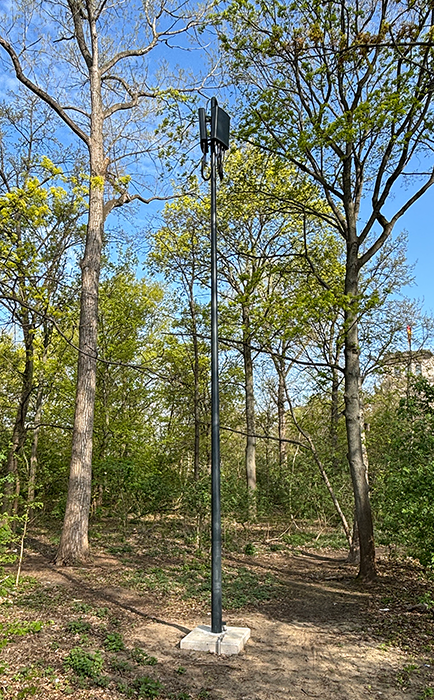
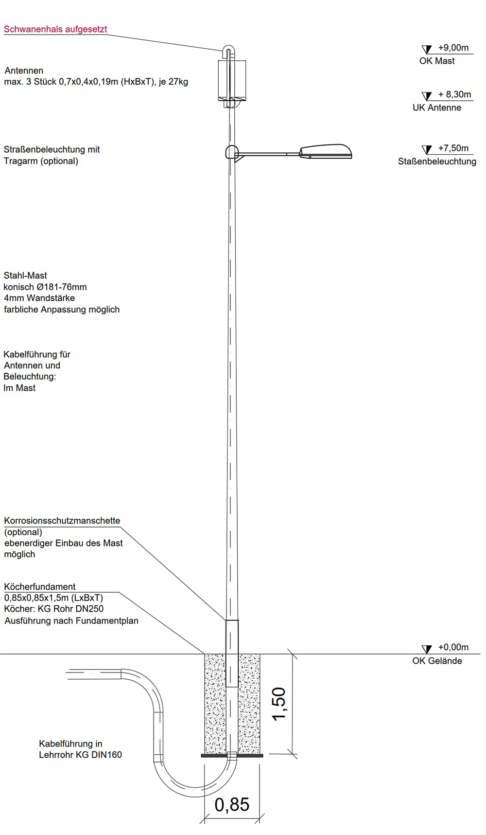
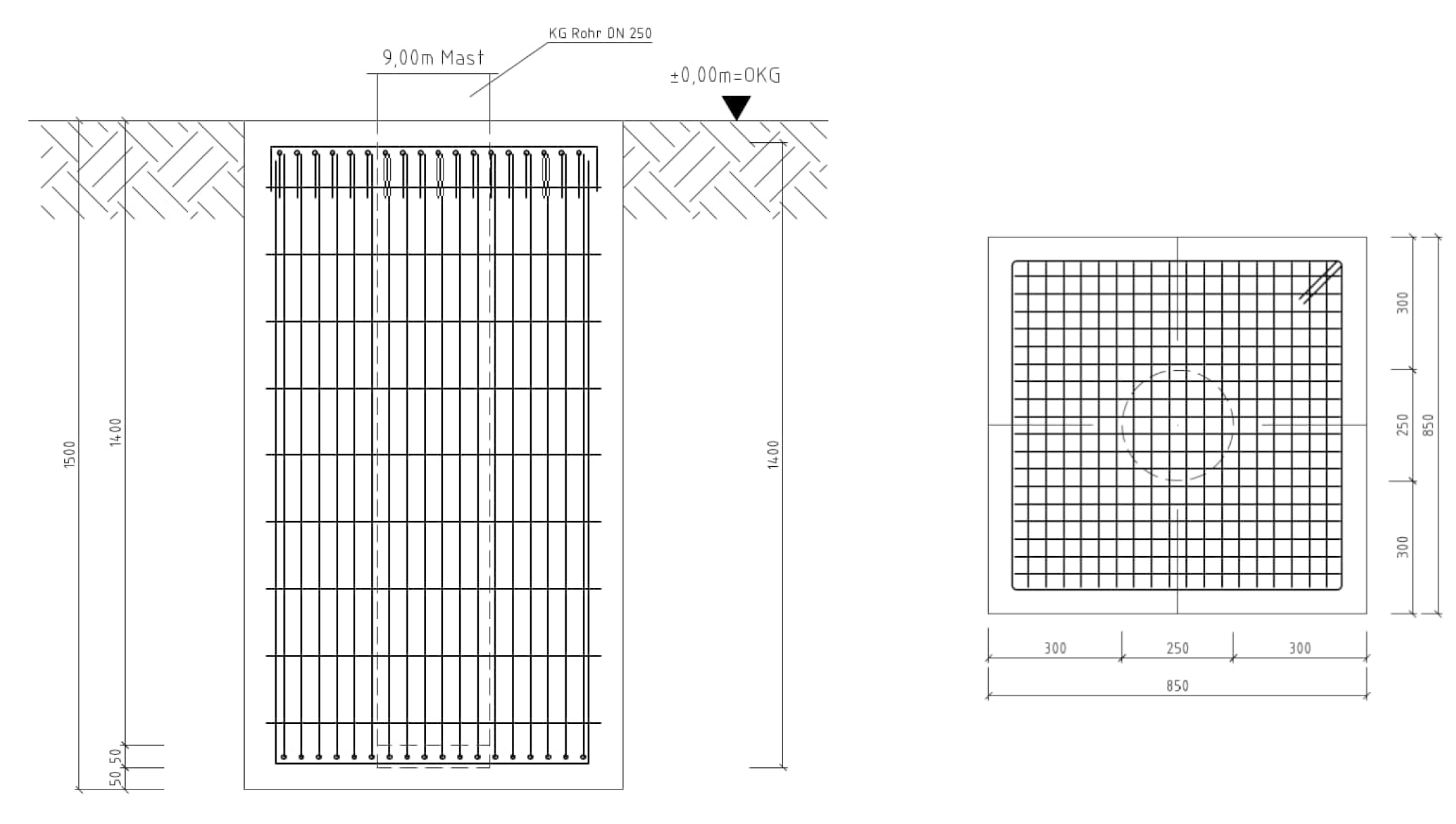
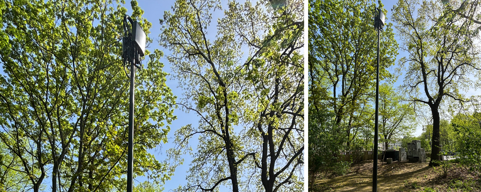
The City Mast has been specifically designed for use in urban environments: Its structure and appearance are modelled on a standard street lamp and, if desired, it can actually be used as such by installing street lighting at 7.50 metres above ground level. Its unobtrusive appearance allows it to blend perfectly into its surroundings in urban areas and makes it ideal for the installation of microcells. As the mast height is less than 10 metres, no building permit is required for the conical steel tubular mast. The foundation type used is a sleeve foundation.
read moreless
| Mast heights | |
|---|---|
|
System height [m] |
9 |
|
Gewicht [kg] |
150 |
| Footprint; montage of street lamp optional | |
|---|---|
|
Mast [m²] |
0,85 |
| Foundations; embedment depth 1,5m | |
|---|---|
|
Width/Length [m] |
0,85 |
|
Slab thickness [m] |
1,5 |
| Implementation times | |||||
|---|---|---|---|---|---|
|
Site survey |
Prerequisites |
Order intake |
|||
|
Calendar days |
14 |
||||
|
Conceptual design |
Prerequisites |
Carrying out the structural inspection |
|||
|
Calendar days |
45 |
||||
|
Detailed design |
Prerequisites |
Approval of the conceptual design |
|||
|
Calendar days |
14 |
||||
|
Start of construction |
Prerequisites |
Approval of the detailed design |
|||
|
Calendar days |
30 |
||||
|
Construction period |
Prerequisites |
Start of construction |
|||
|
Calendar days |
20 |
||||
Standards:
- Verification in accordance with DIN EN 1993-3;
- Wind zone II;
- Terrain category II/III
- Ice zone IV.
-
- Systemzeichnung Citymast
-
- Fundament Citymast
Current news

EQOS Energie modernises catenary system at the Neulengbach railway station
Conversion to cross spans during ongoing railway operations | Increased system availability through renewal of the entire catenary system | A EUR 4 million investment in modern catenary technology for ÖBB Infrastruktur AG

EQOS Energie provides maximum voltage for SuedOstLink with a 525-kV overhead line
EQOS Energie is constructing its first 525-kV overhead line over almost eight kilometres for 50Hertz | EQOS Energie employs its own temporary structures to maintain the power supply | Environmentally friendly construction methods to minimize impact on nature and landscape
read more »
EQOS Energie provides new power for Bonn’s rail network
Stronger catenary lines for the northern part of the city | New masts and improved power transmission over a length of 2.5 kilometres | Renovation work in the midst of city traffic poses a particular challenge